
3D-Printed Super-Wideband Spidron Fractal Cube Antenna with Laminated Copper
3D-Printed Super-Wideband Spidron Fractal Cube Antenna with Laminated Copper
In this paper, a 3D-printed super-wideband (SWB) Spidron fractal cube antenna is proposed. The Spidron fractal configuration is utilized as a self-complementary structure on each face of a 3D frame to attain SWB characteristics. The antenna is excited through a tapered microstrip balun for both mode transforming and impedance matching.
A prototype of the proposed antenna, including the 3D frame fabricated with the help of a 3D printer and Spidron fractal patches made of copper tape, is experimentally verified. The measured−10 dB reflection ratio bandwidth is 34:1 (0.44–15.38 GHz). The peak gain varies from 3.42 to 9.29 dBi within the operating frequency bandwidth. The measured radiation patterns are nearly omnidirectional at all operating frequency bands.
ANTENNA DESIGN
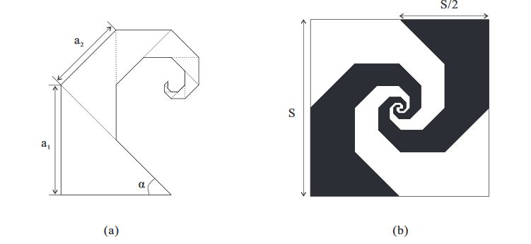
Figure 1. Geometry of (a) the Spidron fractal; (b) the self-complementary structure with the Spidron fractal
Figure 1a shows the concept of the Spidron fractal, depicting a planar figure that includes a series of contiguous right triangles which are scaled down and added to the hypotenuse of a larger triangle. Each triangle has the identical angular factor of α, with the down-scaling factor δ defined as follows.
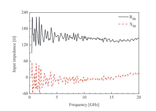
Figure 3. Input impedance of the proposed antenna as simulated by a lumped port
Figure 3 shows the simulated input impedance of the proposed antenna as fed by a lumped port. As can be observed, the real part (R in) and imaginary part (X in) of the input impedance are around 145-Ω and 0-Ω, respectively. Hence, it is necessary to design a balun to match the impedance of the SMA connector (with the characteristic impedance of 50-Ω) and the input impedance of the antenna. Moreover, the unbalanced mode is excited from the SMA connector, but a balanced mode is needed because the proposed antenna operates as a dipole antenna.
EXPERIMENTAL RESULTS AND DISCUSSION
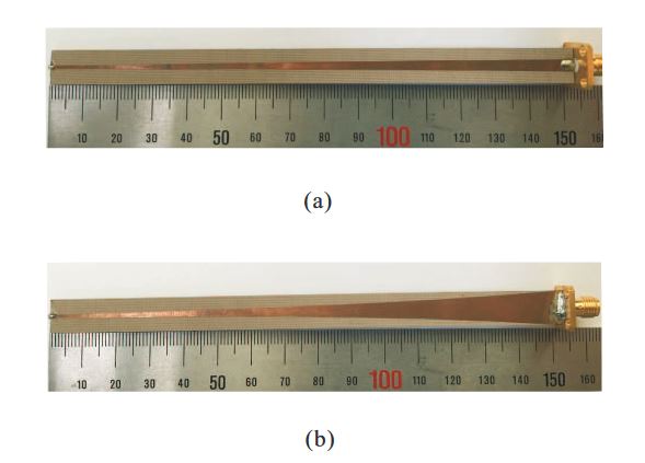
Figure 5. Photographs of the proposed balun: (a) Top side; (b) Bottom side
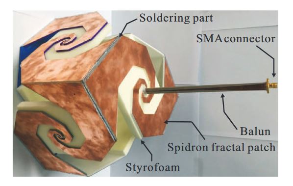
Figure 6. Photograph of the proposed antenna
The thickness of the 3D frame was set to 2.5 mm in consideration of both the time required for printing as well as durability. The Spidron fractal patches—consisting of copper tape—were directly pasted onto the 3D frame and connected by soldering. To support the 3D frame, styrofoam was attached to the inner side of the Spidron fractal face. The interior of the Spidron fractal cube was empty except for the portion where the Styrofoam was located. Photographs of the fabricated balun and antenna are presented in Figures 5 and 6, respectively.