
Arduino clock and temperature monitor using DS3231 and Nokia 5110 LCD
Arduino clock and temperature monitor using DS3231 and Nokia 5110 LCD
In the last Arduino project I built a simple real time clock using DS1307 RTC and NOKIA 5110 LCD (link is below) and in this project I’m going to show how to build a real time clock with temperature monitor using Arduino, DS3231 RTC chip and the same LCD display (Nokia 5110).
The DS3231 is more accurate than the DS1307 due to its built-in temperature sensor. It also (the DS3231) keeps time running if the main power source is down. It also uses I2C interface to communicate with the master device which is in this case the Arduino.
To see how to interface Arduino with Nokia 5110 LCD, visit the following post:
Interfacing Arduino with Nokia 5110 LCD
And to see how to interface Arduino with DS3231 for the first time, take a look at this post:
Arduino and DS3231 real time clock
The link below shows how to interface Arduino with DS1307 RTC and Nokia 5110 LCD:
Arduino clock with NOKIA 5110 LCD and DS1307 RTC
Hardware Required:
- Arduino board
- Nokia 5110 LCD screen
- DS3231 board —-> DS3231 RTC datasheet
- 5 x 3.3k ohm resistor
- 5 x 2.2k ohm resistor
- 2 x push button
- 3V coin cell battery
- Breadboard
- Jumper wires
Arduino with DS3231 and Nokia 5110 LCD circuit:
The following image shows project circuit schematic diagram.
The two push buttons B1 and B2 are for setting time and date. The two buttons are connected to Arduino pin 9 and pin 8 respectively for B1 and B2.
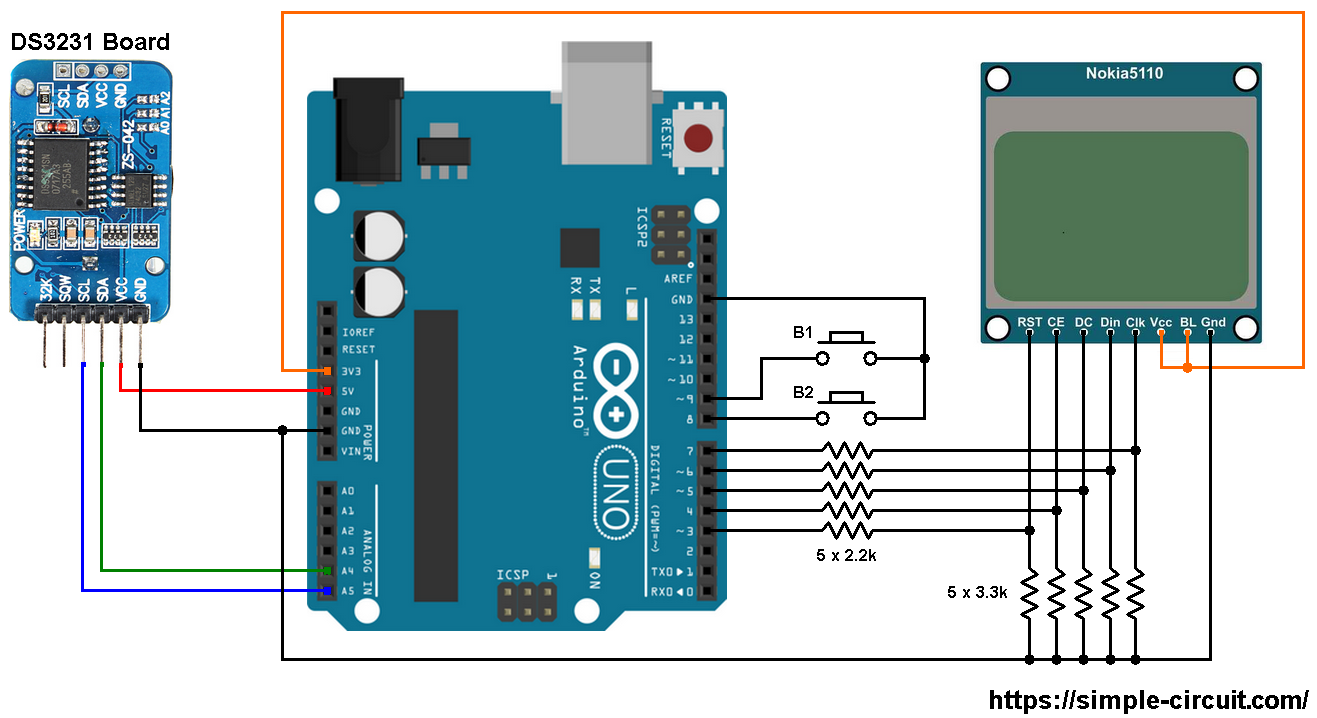
The Nokia 5110 LCD which is shown in the circuit diagram has 8 pins (from left to right): RST (reset), CE (chip enable), DC (or D/C: data/command), Din (data in), Clk (clock), VCC (3.3V), BL (back light) and Gnd (ground).
This LCD works with 3.3V only (power supply and control lines). The LCD module is supplied with 3.3V which comes from the Arduino board (VCC pin of the LCD is connected to Arduino 3.3V pin), BL pin is also connected to 3.3V.
All Arduino UNO board output pins are 5V, connecting a 5V pin to the Nokia 5110 LCD could damage its controller circuit.
To connect the Arduino to the LCD module and for the LCD safety, I used voltage divider for each line which means there are 5 voltage dividers. Each voltage divider consists of 2.2k and 3.3k resistors, this drops the 5V into 3V which is sufficient.
Nokia 5110 LCD pins are connected to Arduino UNO board as follows (each one through voltage divider):
RST (reset) pin is connected to Arduino digital pin 3
CE (chip enable) pin is connected to Arduino digital pin 4
DC (data/command) pin is connected to Arduino digital pin 5
DIN (data in) pin is connected to Arduino digital pin 6
CLK (clock) pin is connected to Arduino digital pin 7
Arduino with DS3231 and Nokia 5110 LCD code:
The Arduino code below doesn’t use any library for the DS3231 RTC chip.
The following Arduino code requires 2 libraries from Adafruit Industries:
The first library is a driver for the Nokia 5110 LCD (PCD8544 controller) which can be installed from Arduino IDE library manager (Sketch —> Include Library —> Manage Libraries …, in the search box write “nokia” and install the one from Adafruit).
The second library is Adafruit graphics library which can be installed also from Arduino IDE library manager.
The previous 2 libraries can also be installed manually, download links are below:
Adafruit Nokia 5110 LCD library —-> direct link
Adafruit graphics library —-> direct link
After the download, go to Arduino IDE —> Sketch —> Include Library —> Add .ZIP Library … and browse for the .zip file (previously downloaded).
The same thing for the other library file.
In the code there are total of 4 libraries, they’re included in the code as follows:
|
1
2
3
4
|
#include <Wire.h> // include Wire library (required for I2C devices)
#include <SPI.h> // include SPI library
#include <Adafruit_GFX.h> // include adafruit graphics library
#include <Adafruit_PCD8544.h> // include adafruit PCD8544 (Nokia 5110) library
|
And the two push buttons are defined in the code as shown below:
|
1
2
3
|
// button definitions
#define button1 9 // button B1 is connected to Arduino pin 9
#define button2 8 // button B2 is connected to Arduino pin 8
|
Full Arduino code:
|
1
2
3
4
5
6
7
8
9
10
11
12
13
14
15
16
17
18
19
20
21
22
23
24
25
26
27
28
29
30
31
32
33
34
35
36
37
38
39
40
41
42
43
44
45
46
47
48
49
50
51
52
53
54
55
56
57
58
59
60
61
62
63
64
65
66
67
68
69
70
71
72
73
74
75
76
77
78
79
80
81
82
83
84
85
86
87
88
89
90
91
92
93
94
95
96
97
98
99
100
101
102
103
104
105
106
107
108
109
110
111
112
113
114
115
116
117
118
119
120
121
122
123
124
125
126
127
128
129
130
131
132
133
134
135
136
137
138
139
140
141
142
143
144
145
146
147
148
149
150
151
152
153
154
155
156
157
158
159
160
161
162
163
164
165
166
167
168
169
170
171
172
173
174
175
176
177
178
179
180
181
182
183
184
185
186
187
188
189
190
191
192
193
194
195
196
197
198
199
200
201
202
203
204
205
206
207
208
209
210
211
212
213
214
215
216
217
218
219
220
221
222
223
224
225
226
227
228
229
230
231
232
233
234
235
236
237
238
239
240
241
242
243
244
245
246
247
248
249
250
251
252
253
254
255
256
257
258
259
260
261
262
263
264
265
266
267
268
269
270
271
272
273
274
275
|
/*
* Arduino real time clock with Nokia 5110 LCD and DS3231.
* This code works also with DS3232.
* This is a free software with NO WARRANTY.
* http://simple-circuit.com/
*/
#include <Wire.h> // include Wire library (required for I2C devices)
#include <SPI.h> // include SPI library
#include <Adafruit_GFX.h> // include adafruit graphics library
#include <Adafruit_PCD8544.h> // include adafruit PCD8544 (Nokia 5110) library
// Nokia 5110 LCD module connections (CLK, DIN, D/C, CS, RST)
Adafruit_PCD8544 display = Adafruit_PCD8544(7, 6, 5, 4, 3);
// button definitions
#define button1 9 // button B1 is connected to Arduino pin 9
#define button2 8 // button B2 is connected to Arduino pin 8
void setup()
{
pinMode(button1, INPUT_PULLUP);
pinMode(button2, INPUT_PULLUP);
delay(1000); // wait 1 second
Wire.begin(); // join I2C bus
// initialize the display
display.begin();
// you can change the contrast around to adapt the display
// for the best viewing!
display.setContrast(50);
display.clearDisplay(); // clear the screen and buffer
display.display();
display.setTextSize(1);
display.setTextColor(BLACK, WHITE);
display.setCursor(28, 16);
display.print(“TIME:”);
display.setCursor(13, 32);
display.print(“CHIP TEMP:”);
display.display();
}
// variable declarations
char Time[] = ” : : “;
char Date[] = ” / /20 “;
char Temp[] = “000.00”;
char temperature_msb;
byte i, second, minute, hour, w_day, day, month, year, temperature_lsb;
// a small function for button1 (B1) debounce
bool debounce ()
{
byte count = 0;
for(byte i = 0; i < 5; i++)
{
if ( !digitalRead(button1) )
count++;
delay(10);
}
if(count > 2) return 1;
else return 0;
}
// function for display day of the week
void day_display()
{
switch(w_day)
{
case 1: draw_text(12, 0, ” SUNDAY “); break;
case 2: draw_text(12, 0, ” MONDAY “); break;
case 3: draw_text(15, 0, ” TUESDAY “); break;
case 4: draw_text(15, 0, “WEDNESDAY”); break;
case 5: draw_text(12, 0, ” THURSDAY “); break;
case 6: draw_text(12, 0, ” FRIDAY “); break;
default: draw_text(12, 0, ” SATURDAY “);
}
}
void RTC_display()
{
// convert BCD to decimal
second = (second >> 4) * 10 + (second & 0x0F);
minute = (minute >> 4) * 10 + (minute & 0x0F);
hour = (hour >> 4) * 10 + (hour & 0x0F);
day = (day >> 4) * 10 + (day & 0x0F);
month = (month >> 4) * 10 + (month & 0x0F);
year = (year >> 4) * 10 + (year & 0x0F);
// end conversion
// update time array
Time[7] = second % 10 + ‘0’;
Time[6] = second / 10 + ‘0’;
Time[4] = minute % 10 + ‘0’;
Time[3] = minute / 10 + ‘0’;
Time[1] = hour % 10 + ‘0’;
Time[0] = hour / 10 + ‘0’;
// update date array
Date[9] = year % 10 + ‘0’;
Date[8] = year / 10 + ‘0’;
Date[4] = month % 10 + ‘0’;
Date[3] = month / 10 + ‘0’;
Date[1] = day % 10 + ‘0’;
Date[0] = day / 10 + ‘0’;
int chip_temp = temperature_msb << 2 | temperature_lsb >> 6;
if (chip_temp < 0)
{ // if temperature is negative
chip_temp = abs(chip_temp); // absolute value
Temp[0] = ‘-‘; // put minus sign
}
else
Temp[0] = ‘ ‘; // put space
Temp[1] = chip_temp / 40 + ‘0’; // chip_temp/40 = (chip_temp/4)/10 –> get tens
Temp[2] = (chip_temp / 4) % 10 + ‘0’; // –> get ones
Temp[4] = (chip_temp * 5) / 2 % 10 + ‘0’; // chip_temp*5/2 = (chip_temp/4)*10 –> get tenths
Temp[5] = (chip_temp * 25) % 10 + ‘0’; // chip_temp*25 = (chip_temp/4)*100 –> get hundredths
draw_text(12, 8, Date); // print date
draw_text(18, 24, Time); // print time
draw_text(15, 40, Temp); // print chip temperature
display.drawRect(53, 40, 3, 3, BLACK); // print degree symbol ( ° )
draw_text(58, 40, “C”); // print ‘C’
}
void blink_parameter()
{
byte j = 0;
while(j < 100 && digitalRead(button1) && digitalRead(button2))
{
j++;
delay(5);
}
}
byte edit(byte x_pos, byte y_pos, byte parameter)
{
char text[3];
sprintf(text,“%02u”, parameter);
while(debounce()); // call debounce function (wait for B1 to be released)
while(1)
{
while(!digitalRead(button2))
{
parameter++;
if(i == 0 && parameter > 31) // if date > 31 ==> date = 1
parameter = 1;
if(i == 1 && parameter > 12) // if month > 12 ==> month = 1
parameter = 1;
if(i == 2 && parameter > 99) // if year > 99 ==> year = 0
parameter = 0;
if(i == 3 && parameter > 23) // if hours > 23 ==> hours = 0
parameter = 0;
if(i == 4 && parameter > 59) // if minutes > 59 ==> minutes = 0
parameter = 0;
sprintf(text,“%02u”, parameter);
draw_text(x_pos, y_pos, text);
delay(200); // wait 200ms
}
draw_text(x_pos, y_pos, ” “);
blink_parameter();
draw_text(x_pos, y_pos, text);
blink_parameter();
if(!digitalRead(button1)) // if button B1 is pressed
if(debounce()) // call debounce function (make sure if B1 is pressed)
{
i++; // increment ‘i’ for the next parameter
return parameter; // return parameter value and exit
}
}
}
// print text on the LCD
void draw_text(byte x_pos, byte y_pos, char *text)
{
display.setCursor(x_pos, y_pos);
display.print(text);
display.display();
}
// main loop
void loop()
{
if(!digitalRead(button1)) // if button B1 is pressed
if(debounce()) // call debounce function (make sure if B1 is pressed)
{
i = 0;
while(debounce()); // call debounce function (wait for button B1 to be released)
while(1)
{
while( !digitalRead(button2) ) // while button B2 pressed
{
w_day++; // increment w_day
if(w_day > 7)
w_day = 1;
day_display(); // call day_display function
delay(500); // wait 500 ms
}
draw_text(15, 0, ” “);
blink_parameter(); // call blink_parameter function
day_display(); // call day_display function
blink_parameter(); // call blink_parameter function
if( !digitalRead(button1) ) // if button B1 is pressed
break;
}
day = edit(12, 8, day); // edit date
month = edit(30, 8, month); // edit month
year = edit(60, 8, year); // edit year
hour = edit(18, 24, hour); // edit hours
minute = edit(36, 24, minute); // edit minutes
// convert decimal to BCD
minute = ((minute / 10) << 4) + (minute % 10);
hour = ((hour / 10) << 4) + (hour % 10);
day = ((day / 10) << 4) + (day % 10);
month = ((month / 10) << 4) + (month % 10);
year = ((year / 10) << 4) + (year % 10);
// end conversion
while(debounce()); // call debounce function (wait for button B1 to be released)
// write data to DS1307 RTC
Wire.beginTransmission(0x68); // start I2C protocol with DS1307 address
Wire.write(0); // send register address
Wire.write(0); // reset sesonds and start oscillator
Wire.write(minute); // write minute
Wire.write(hour); // write hour
Wire.write(w_day); // write day
Wire.write(day); // write date
Wire.write(month); // write month
Wire.write(year); // write year
Wire.endTransmission(); // stop transmission and release the I2C bus
delay(200); // wait 200ms
}
// read time and date
Wire.beginTransmission(0x68); // start I2C protocol with DS1307 address
Wire.write(0); // send register address
Wire.endTransmission(false); // I2C restart
Wire.requestFrom(0x68, 7); // request 7 bytes from DS1307 and release I2C bus at end of reading
second = Wire.read(); // read seconds from register 0
minute = Wire.read(); // read minuts from register 1
hour = Wire.read(); // read hour from register 2
w_day = Wire.read(); // read day from register 3
day = Wire.read(); // read date from register 4
month = Wire.read(); // read month from register 5
year = Wire.read(); // read year from register 6
// read chip temperature
Wire.beginTransmission(0x68); // start I2C protocol with DS3231 address
Wire.write(0x11); // send register address
Wire.endTransmission(false); // I2C restart
Wire.requestFrom(0x68, 2); // request 2 bytes from DS3231 and release I2C bus at end of reading
temperature_msb = Wire.read(); // read temperature MSB
temperature_lsb = Wire.read(); // read temperature LSB
day_display(); // print day of the week
RTC_display(); // print time & date
delay(100); // wait 100 ms
}
// end of code.
|
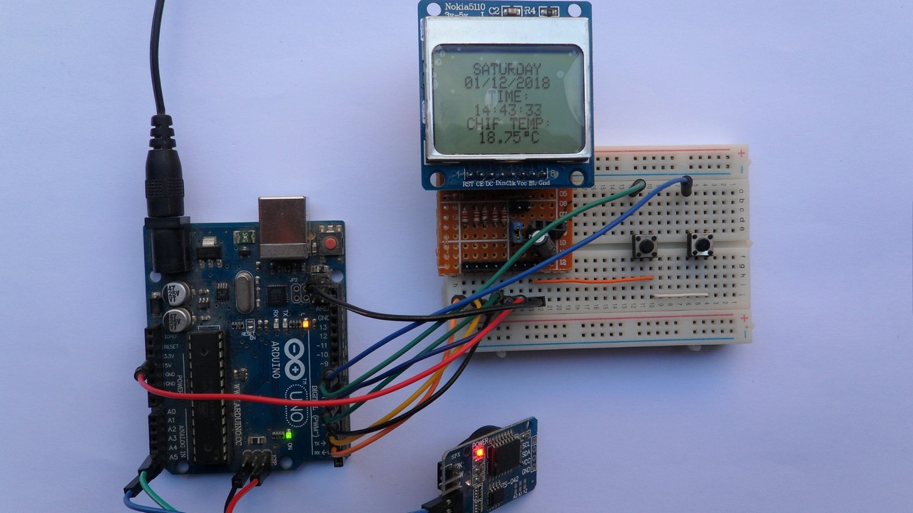
The following video shows a simple hardware circuit of this project:
and the one below shows Proteus simulation (note that simulation circuit is not the same as real hardware circuit, hardware circuit diagram is shown above):
Proteus simulation file download link is below, use version 8.6 or later to open it:
Arduino with Nokia 5110 LCD and DS3231 RTC