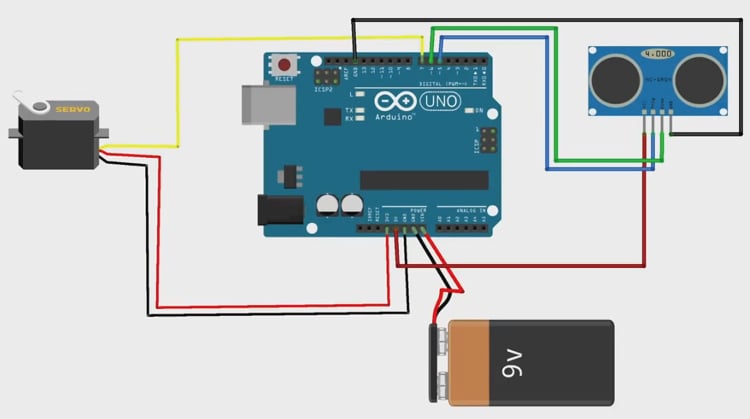
Circuit Diagram
Circuit Diagram
The image below shows the Arduino circuit diagram for building a smart bin. As you can see it is very simple, it just has an ultrasonic sensor and a servo motor connected to the Arduino UNO, and the whole setup is powered by a 9V battery.
You can make the connections as shown in the circuit diagram, if you have any doubts you can also follow the connection diagram below
| Component | Pin | Arduino Connection |
| Servo Motor | Yellow Wire | Digital Pin 7 |
| Servo Motor | Red Wire | 5V |
| Servo Motor | Black Wire | GND |
| Ultrasonic Sensor | VCC pin | 5V |
| Ultrasonic Sensor | GND pin | GND |
| Ultrasonic Sensor | Trig pin | Digital Pin 5 |
| Ultrasonic Sensor | Echo pin | Digital Pin 6 |
| 9V Battery | Positive | Vin |
| 9V Battery | Negative | GND |

