
Interfacing Arduino with LM35 sensor and 7-segment display
Interfacing Arduino with LM35 sensor and 7-segment display
This topic shows how to make a simple temperature measurement station using Arduino UNO board and LM35 analog temperature sensor where temperature value is displayed on 3-digit 7-segment display.
The LM35 temperature sensor is a three pin device (VCC, OUT and GND) with an output voltage linearly related to Centigrade temperature. Since the LM35 output varies with dependent to the temperature, we need an ADC (Analog-to-Digital Converter) module to measure this voltage.
To see how to interface Arduino with 7-segment display visit the following post:
Interfacing Arduino with 7-segment display | 4-Digit counter example
Also for more details about the LM35 sensor and how to interface it with Arduino, see this project:
Arduino and LM35 temperature sensor interfacing
Hardware Required:
- Arduino UNO board
- 3-Digit (or 4-digit) common anode 7-segment display
- LM35 temperature sensor —-> datasheet
- 3 x PNP transistor (2SA1015, 2S9015, 2N3906 …)
- 8 x 100 ohm resistor
- 3 x 4.7k ohm resistor
- Breadboard
- Jumper wires
Interfacing Arduino with LM35 sensor and 7-segment display circuit:
The image below shows project circuit schematic diagram.
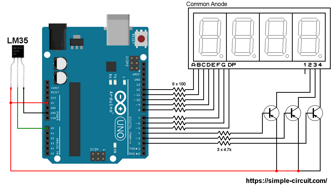
The LM35 sensor has 3 pins (from left to right):
Pin 1 is power supply pin, connected to Arduino 5V pin
Pin 2: output pin, connected to Arduino analog pin 0 (A0)
Pin 3: GND (ground), connected to Arduino GND pin.
The 3 transistors are of the same type (PNP).
Interfacing Arduino with LM35 sensor and 7-segment display code:
The Arduino code below doesn’t use any library for the 7-segment display.
Reading voltage quantity using the ADC gives a number between 0 and 1023 (10-bit resolution), 0V is represented by 0 and 1.1V is represented by 1023 (ADC positive reference is 1.1V) . Converting back the ADC digital value is easy, we can use the following equation:
Voltage (in Volts) = ADC reading * 1.1 / 1023
Multiplying the previous result by 100 (LM35 scale factor is 10mV/°C = 0.01V/°C) gives the actual temperature:
Temperature( °C) = ADC reading * 0.1075 , or
Temperature( °C) = ADC reading / 9.3
where: 0.1075 = 100 * 1.1 / 1023 and 9.3 = 1 / 0.1075
To use the internal 1.1V reference I used the command: analogReference(INTERNAL);
In this example I used one number after the decimal point, multiplying the temperature by 10 will remove the decimal point, so the final result is:
|
1
|
temp = 10 * analogRead(LM35_pin) / 9.3;
|
The decimal point is displayed on the screen before printing the last digit (most right) which means it displayed with digit 2.
Full Arduino code:
|
1
2
3
4
5
6
7
8
9
10
11
12
13
14
15
16
17
18
19
20
21
22
23
24
25
26
27
28
29
30
31
32
33
34
35
36
37
38
39
40
41
42
43
44
45
46
47
48
49
50
51
52
53
54
55
56
57
58
59
60
61
62
63
64
65
66
67
68
69
70
71
72
73
74
75
76
77
78
79
80
81
82
83
84
85
86
87
88
89
90
91
92
93
94
95
96
97
98
99
100
101
102
103
104
105
106
107
108
109
110
111
112
113
114
115
116
117
118
119
120
121
122
123
124
125
126
127
128
129
130
131
132
133
134
135
136
137
138
139
140
141
142
143
144
145
146
147
148
149
150
151
152
153
154
155
156
157
158
159
160
161
162
163
164
165
166
167
168
169
170
171
172
173
174
175
176
177
178
179
180
181
182
183
184
185
186
187
188
189
190
191
192
193
194
195
196
197
198
199
200
201
202
203
204
205
206
207
208
209
|
/*
* Interfacing Arduino with LM35 temperature sensor and 7-segment display.
* Common anode 7-segment display is used.
* This is a free software with NO WARRANTY.
* http://simple-circuit.com/
*/
// define LM35 data pin connection
#define LM35_pin A0
// segment pins definitions
#define SegA 12
#define SegB 11
#define SegC 10
#define SegD 9
#define SegE 8
#define SegF 7
#define SegG 6
#define SegDP 5
// common pins of the three digits definitions
#define Dig1 4
#define Dig2 3
#define Dig3 2
// variable declarations
byte current_digit;
int temp;
void setup()
{
pinMode(SegA, OUTPUT);
pinMode(SegB, OUTPUT);
pinMode(SegC, OUTPUT);
pinMode(SegD, OUTPUT);
pinMode(SegE, OUTPUT);
pinMode(SegF, OUTPUT);
pinMode(SegG, OUTPUT);
pinMode(SegDP, OUTPUT);
pinMode(Dig1, OUTPUT);
pinMode(Dig2, OUTPUT);
pinMode(Dig3, OUTPUT);
disp_off(); // turn off the display
// Timer1 module overflow interrupt configuration
TCCR1A = 0;
TCCR1B = 1; // enable Timer1 with prescaler = 1 ( 16 ticks each 1 µs)
TCNT1 = 0; // set Timer1 preload value to 0 (reset)
TIMSK1 = 1; // enable Timer1 overflow interrupt
analogReference(INTERNAL); // set positive reference voltage to 1.1V
}
ISR(TIMER1_OVF_vect) // Timer1 interrupt service routine (ISR)
{
disp_off(); // turn off the display
switch (current_digit)
{
case 1:
disp((temp / 100) % 10);
digitalWrite(Dig1, LOW); // turn on digit 1
break;
case 2:
disp( (temp / 10) % 10); // prepare to display digit 2
digitalWrite(SegDP, LOW); // print decimal point ( . )
digitalWrite(Dig2, LOW); // turn on digit 2
break;
case 3:
disp(temp % 10); // prepare to display digit 3
digitalWrite(Dig3, LOW); // turn on digit 3
}
current_digit = (current_digit % 3) + 1;
}
// main loop
void loop()
{
temp = 10 * analogRead(LM35_pin) / 9.3; // read analog voltage and convert it to °C ( 9.3 = 1023/(1.1*100) )
delay(1000); // wait 1 second
}
void disp(byte number)
{
switch (number)
{
case 0: // print 0
digitalWrite(SegA, LOW);
digitalWrite(SegB, LOW);
digitalWrite(SegC, LOW);
digitalWrite(SegD, LOW);
digitalWrite(SegE, LOW);
digitalWrite(SegF, LOW);
digitalWrite(SegG, HIGH);
digitalWrite(SegDP, HIGH);
break;
case 1: // print 1
digitalWrite(SegA, HIGH);
digitalWrite(SegB, LOW);
digitalWrite(SegC, LOW);
digitalWrite(SegD, HIGH);
digitalWrite(SegE, HIGH);
digitalWrite(SegF, HIGH);
digitalWrite(SegG, HIGH);
digitalWrite(SegDP, HIGH);
break;
case 2: // print 2
digitalWrite(SegA, LOW);
digitalWrite(SegB, LOW);
digitalWrite(SegC, HIGH);
digitalWrite(SegD, LOW);
digitalWrite(SegE, LOW);
digitalWrite(SegF, HIGH);
digitalWrite(SegG, LOW);
digitalWrite(SegDP, HIGH);
break;
case 3: // print 3
digitalWrite(SegA, LOW);
digitalWrite(SegB, LOW);
digitalWrite(SegC, LOW);
digitalWrite(SegD, LOW);
digitalWrite(SegE, HIGH);
digitalWrite(SegF, HIGH);
digitalWrite(SegG, LOW);
digitalWrite(SegDP, HIGH);
break;
case 4: // print 4
digitalWrite(SegA, HIGH);
digitalWrite(SegB, LOW);
digitalWrite(SegC, LOW);
digitalWrite(SegD, HIGH);
digitalWrite(SegE, HIGH);
digitalWrite(SegF, LOW);
digitalWrite(SegG, LOW);
digitalWrite(SegDP, HIGH);
break;
case 5: // print 5
digitalWrite(SegA, LOW);
digitalWrite(SegB, HIGH);
digitalWrite(SegC, LOW);
digitalWrite(SegD, LOW);
digitalWrite(SegE, HIGH);
digitalWrite(SegF, LOW);
digitalWrite(SegG, LOW);
digitalWrite(SegDP, HIGH);
break;
case 6: // print 6
digitalWrite(SegA, LOW);
digitalWrite(SegB, HIGH);
digitalWrite(SegC, LOW);
digitalWrite(SegD, LOW);
digitalWrite(SegE, LOW);
digitalWrite(SegF, LOW);
digitalWrite(SegG, LOW);
digitalWrite(SegDP, HIGH);
break;
case 7: // print 7
digitalWrite(SegA, LOW);
digitalWrite(SegB, LOW);
digitalWrite(SegC, LOW);
digitalWrite(SegD, HIGH);
digitalWrite(SegE, HIGH);
digitalWrite(SegF, HIGH);
digitalWrite(SegG, HIGH);
digitalWrite(SegDP, HIGH);
break;
case 8: // print 8
digitalWrite(SegA, LOW);
digitalWrite(SegB, LOW);
digitalWrite(SegC, LOW);
digitalWrite(SegD, LOW);
digitalWrite(SegE, LOW);
digitalWrite(SegF, LOW);
digitalWrite(SegG, LOW);
digitalWrite(SegDP, HIGH);
break;
case 9: // print 9
digitalWrite(SegA, LOW);
digitalWrite(SegB, LOW);
digitalWrite(SegC, LOW);
digitalWrite(SegD, LOW);
digitalWrite(SegE, HIGH);
digitalWrite(SegF, LOW);
digitalWrite(SegG, LOW);
digitalWrite(SegDP, HIGH);
}
}
void disp_off()
{
digitalWrite(Dig1, HIGH);
digitalWrite(Dig2, HIGH);
digitalWrite(Dig3, HIGH);
}
// end of code.
|
The following video shows Proteus simulation of this project (simulation circuit is not the same as real hardware circuit, example circuit diagram is shown above):
Proteus simulation file download:
Arduino + LM35 sensor + 7-segment display